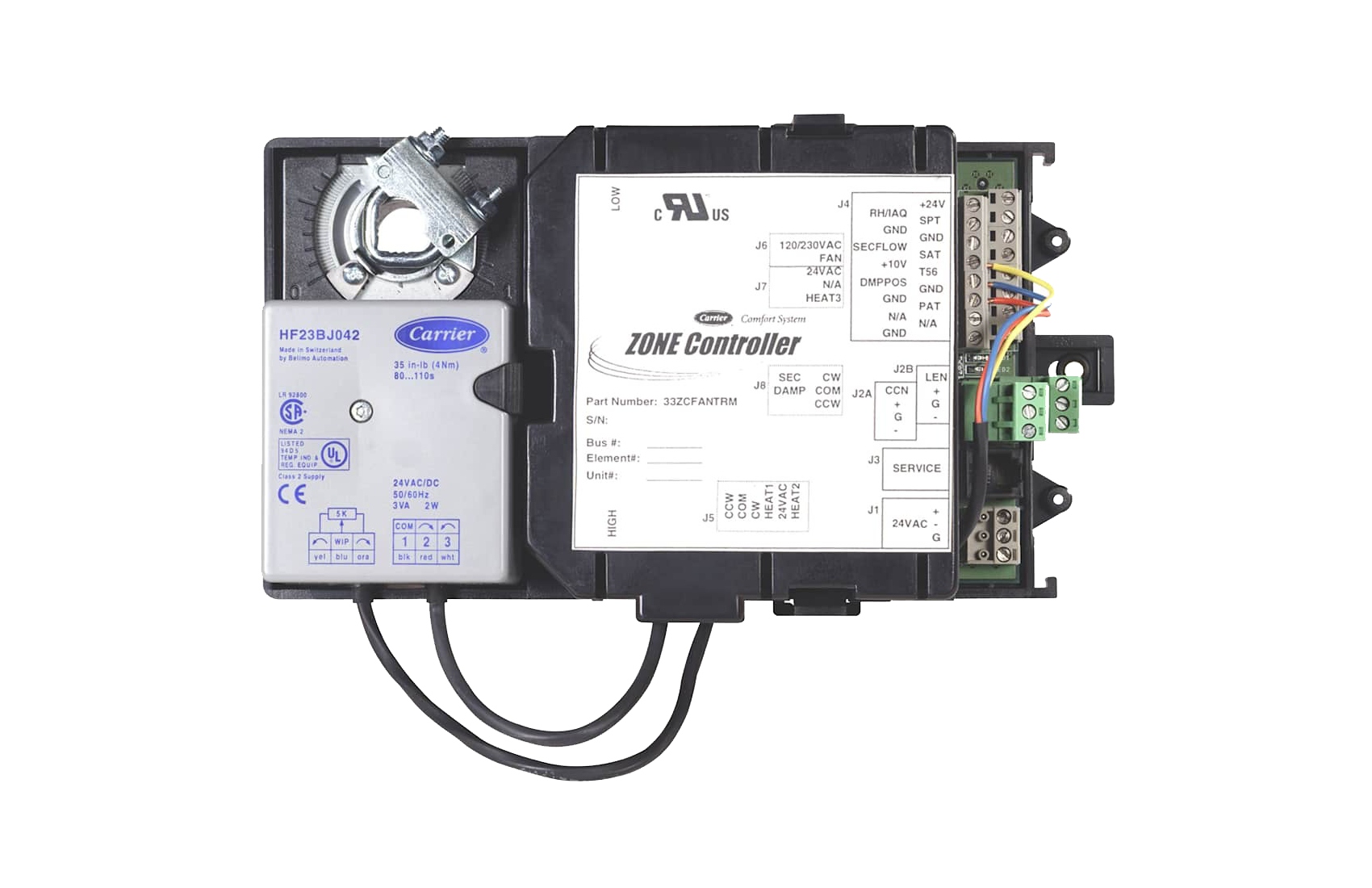
24/7 Commercial Service

call 1-800-379-6484

Find an expert

ComfortID™ Single Duct Air Terminal Zone Controller
33ZCVAVTRM

Product Integrated Controller

The Single Duct Air Terminal Zone Controller provides dedicated control functions for single duct terminals with modulating heat or up to 2 stages of heat. The zone controller is part of the Carrier ComfortID system.

  • Provides Pressure Independent (VAV) control
  • Uses Proportional Integral Derivative (PID) control
  • Mounts directly onto VAV box damper shaft
  • Terminal fan control
  • For terminals up to 9000 cfm or 3.4 sq. ft inlet (primary air)
  • Auxiliary heating control of modulating (floating) hot water, single-position hot water, single or two-stage electric, or zone perimeter heat
  • Quick and easy commissioning and balancing process
  • Automatic self calibration of airflow transducer
  • Capable of stand-alone operation, with supply-air temperature sensor
  • Actuator preassembled to housing
  • Capable of demand controlled ventilation support with field-installed IAQ sensor
  • Easy access to airflow sensor pneumatic connections
  • Uses Carrier Comfort Network (CCN) protocol
  • Capable of high-speed 38.4 kilobaud communications network operation
  • 128 controller maximum system (must be located on same CCN bus segment)
  • Capable of zone humidity control (dehumidification) with field-installed humidity sensor
  • Carrier Linkage System capability
  • Global set point and occupancy scheduling provides a remote occupancy contact input for a field-supplied occupancy sensor
  • Capable of local set point adjustment with field-installed temperature sensor (with temperature offset)
  • Both controller housing and actuator are UL94-5V plenum rated

Wiring Connections

Field wiring is 18 to 22 AWG (American Wire Gage). The zone controller is a NEC (National Electronic Code) Class 2 rated device.

Inputs

  • Space temperature sensor
  • Primary air damper position
  • Airflow sensor (factory installed)
  • Field-installed remote wall sensor set point adjustment
  • Optional supply temperature sensor (required for heat and supply air monitoring)
  • Optional primary air temperature sensor (required for systems which do not utilize a linkage compatible air source)
  • Optional IAQ sensor
  • Optional relative humidity sensor
  • Optional remote occupancy contact input

Outputs

  • Internally factory-wired VAV actuator
  • Heating
    • Modulating (floating) heat
    • Up to 2 stages of heat
    • Single position heat

Power Supply

The power supply is 24 VAC ± 10% at 40 VA (50/60 Hz).

Power Consumption

The power requirement sizing allows for accessory water valves and for the fan contactor. Water valves are limited to 15 VA on both single-position and modulating hot water. The fan contactor is limited to 10 VA (holding) each.

Accuracy

Terminal airflow (nominal cfm) is rated at 1-in. wg (249 kPa) measured velocity pressure. The zone controller is capable of controlling to as low as 10% or as high as 125% of nominal airflow with an accuracy of ± 3% (nominal) at any point within the range.

Hardware (memory)

FLASH EPROM

Differential Pressure Range

0 to 2.0 in. wg (0 to 498 kPa) maximum for the onboard flow sensor.

Specified Sensing Temperature Range

The zone controller space temperature range is –40 to 245 F (–40 to 118 C). The zone controller has an allowable control set point range from 40 to 90 F (4 to 32 C) for heating and 45 to 99 F (7 to 37 C) for cooling.

Communications

The number of controllers is limited to 128 zones maximum, with a limit of 8 systems (Linkage Coordinator configured for at least 2 zones). Bus length may not exceed 4000 ft (1219 m), with no more than 60 devices on any 1000 ft (305 m) section. Optically isolated RS-485 repeaters are required every 1000 ft (305 m).

At 19,200 and 38,400 baud, the number of controllers is limited to 128 maximum, with no limit on the number of Linkage Coordinators. Bus length may not exceed 1000 ft (305 m).

Environmental Ratings

Operating Temperature: 32 to 140 F (0° to 60 C) at 0 to 90% RH (non–condensing) Shipping Temperature: –40 to 185 F (-40 to 85 C) at 0 to 90% RH (non–condensing)

Vibration

Performance vibration:

  • 0.014-in. (0.356 mm) Peak-to-Peak displacement measured at 5 to 31 Hz
  • 0.75 G measured at 31 to 300 Hz

Corrosion

Office environment. Indoor use only.

Approvals

  • Listed under UL 916-PAZX and UL 873
  • Conforms to requirements per European Consortium standards EN50081-1 (CISPR 22, Class B) and EN50082-1 (IEC 801-2, IEC 801-3, and IEC 801-4) for CE mark labeling
  • UL94-5V plenum rated (housing and actuator)

Accessories

  • Conduit box (33ZCCONBOX)
  • Supply air temperature sensor (33ZCSENSAT)
  • Primary air temperature sensor (33ZCSENPAT)
  • Space temperature sensor with override button (33ZCT55SPT)
  • Space temperature sensor with override button and set point adjustment (33ZCT56SPT)