TruVu™ ChillerVu™ Plant Controller TV-PSM


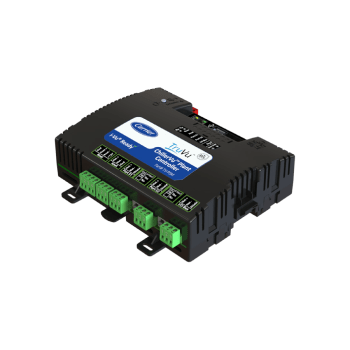
TruVu™ ChillerVu™ Plant Controller
TV-PSM
The TruVu ChillerVu Plant Controller coordinates the functions of all main chiller plant components, providing optimized equipment operation while helping to reduce energy usage and operating costs. The system includes a dedicated chiller plant controller and an extensive library of control programs, graphics, and energy dashboards that can be easily customized to meet the design and specifications of any chiller plant.
The TV-PSM features built-in routing and integration capabilities, along with support for up to nine TruVu MPC I/O expansion modules and a total of 180 input/output points.


System Benefits
- Integrates seamlessly with chiller plant equipment using BACnet and Modbus® protocols
- Fully plug-and-play with the Carrier i-Vu building automation system
- Pre-configured energy dashboards and embedded trends/alarms provide immediate insight on chiller plant performance and aid in troubleshooting/maintenance
Energy Saving Strategies
- Enhanced chiller staging dynamically matches the number of running chillers to building load
- Variable flow pump sequences minimize pump energy consumption
- Staged and variable speed tower fans minimize tower fan energy consumption
- Demand limiting limits plant energy consumption to fixed levels, avoiding excess electrical demand charges
- Pre-configured chilled water setpoint reset; plug and play compatible with Carrier Chilled Water System Optimizer
- Optional soft start ramp loading, chilled water reset, load feathering (Add/Drop), and demand limiting
Easily Customizable for Any Plant
- Easily reconfigure control sequences using EquipmentBuilder and can be fully edited in Snap
- Pre-configured, user editable energy dashboards (actionable plant energy data graphically displayed)
- High quality, automatically generated plant room graphics, requiring minimal user input
Standard Application Library
- Full complement of pre-written plant control sequences
- Chiller Manager with basic and advanced chiller staging sequences
- Pump Manager with control sequences for the primary and secondary chilled and condenser water pumps
- Tower Manager with control sequences for the towers
- Open and Closed Cooling Tower programs for towerspecific control points, including condenser water pumps and other peripheral equipment
- Chiller System – Self contained single chiller application with I/O to control the chiller, pumps and cooling towers
- Carrier proprietary 23XRV Series Counterflow control sequence
Supported Chiller Hardware
- Carrier legacy chillers with native CCN controls connected with UPCs or via i-Vu Open Links
- New generation Carrier PIC chillers (PIC6.x) with native BACnet connectivity
- Third-party chillers that support BACnet protocol (must have accessible BACnet points with correct read/write properties)
- Plants with non-communicating chillers, using fieldinstalled controllers and logic
| BACnet Support | Conforms to the BACnet Building Controller (B-BC), BACnet Router (B-RTR), and BACnet BBMD (B-BBMD) device profiles as defined in BACnet 135-2012 Annex L, Protocol Revision 14 | |
| Communication Ports | Gig-E:10/100/1000 BaseT Ethernet port for BACnet/IP and/or BACnet/Ethernet and/or Modbus TCP/IP communication
S1 Port: High-speed EIA-485 port with End of Net switch for connecting one of the following: » BACnet MS/TP network at 9.6 to 115.2 kbps » Modbus RTU at 9.6 to 115.2 kbps S2 Port: Electrically isolated EIA-485 port with End of Net switch for connecting one of the following » BACnet MS/TP network at 9.6 to 115.2 kbps » Modbus RTU at 9.6 to 115.2 kbps Service Port: 10/100 Base T Ethernet port for system start-up and troubleshooting and local EQT displays Rnet port: Communicate with up to 15 ZS communicating sensor |
USB Port:USB 2.0 host port for alternate local access service, device recovery, memory downloads and local EQT displays
I/O Expansion Options I/O Bus edge connector: Provides communication for up to 9 and power for up to 7 directly-connected TruVu MPC I/O expanders when using a DC power supply I/O Bus port: Provides communication with up to 9 TruVu MPC I/O expanders (externally powered) up to 1,000 feet away Xnet port: Provides communication with up to 6 MPC Open XPIO48 and/or MPC Open XPIO816 expanders up to 100 feet away |
| Third Party Integration | Supports up to 1,500 third-party BACnet points and 200 Modbus points (memory dependent) | |
| Physical | Fire-retardant plastic ABS, UL94-5VA | |
| I/O Expanders | Supports up to 9 TruVu MPC I/O expanders and/or 6 MPC Open XPIO expanders (max 9 total) | |
| Protection | Two fast acting, 5mm x 20mm glass fuses: • A 2A fuse for the TV-MPCXP’s power • A 4A fuse for the I/O bus edge connector. The power and network ports comply with the EMC requirements EN50491-5-2 | |
| Compliance | United States: FCC compliant to Title CFR47, Part 15, Subpart B, Class A; UL Listed, File E143900; CCN PAZX, UL 916, Energy Management Equipment; ANZ: RCM Mark AS/NZS 61000-6-3; Canada: UL Listed File E143900, CCN PAZX7, CAN/CSA C22.2 No. 205 Signal Equip., Industry Canada Compliant ICES-003, Class A; CE Mark Compliant with 2014/30/EU, and RoHS Compliant: 2015/863/EU; UKCA Mark Compliant with Electromagnetic Compatibility Regulations 2016 – Gov.UK and and RoHS for Electrical and Electronic Equipment 2012. | |
| Real-Time Clock | Real-time clock keeps track of time in the event of a power failure for up to 3 days | |
| Environmental Operating Range | Operating: -40 to 158ºF (-40 to 70ºC) 10 to 95% RH, non-condensing | |
| Power Requirements | 24VAC ± 10%, 50-60Hz; 50 VA power consumption; 26VDC ± 10% 15W; Single Class 2 source only, 100 VA or less | |
California residents please see Proposition 65