VVT Zoning System Brochure Low Resolution 1/21
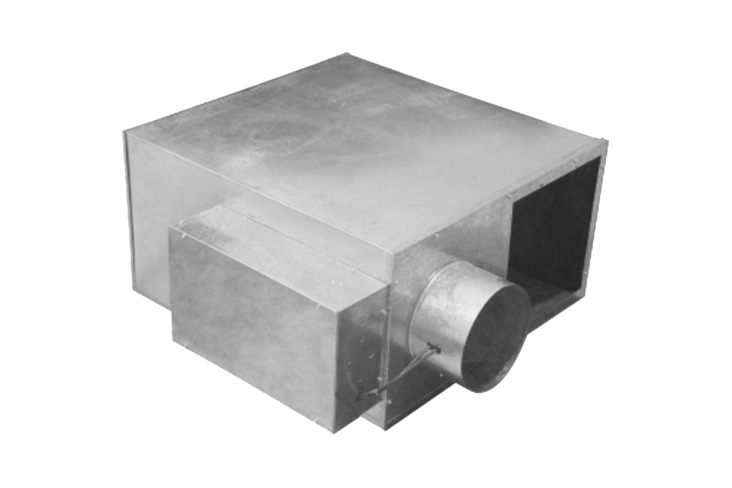
AXIS™ 45M Parallel Fan-Powered Air Terminal
Technical Specifications
At a Glance
Type
Parallel Fan-PoweredAirflow Range
0 - 2,200 CFMFan Airflow
Airflow Range
0 - 3,660 CFMPrimary Airflow
Features
Performance Features
Fan airflow capacities from 50 to 2200 cfm
Primary airflow capacities from 52-3660 cfm
Round inlet sizes from 6 in. through 16 in. diameter
22 gage, galvanized steel casing construction
Suitable for low, medium, or high pressure applications
Linear, multiple-point, averaging velocity sensor with an amplified signal
Damper blade has a flexible gasket for tight airflow shutoff
Damper blade operates over a full 90 degrees
All damper assemblies utilize a solid ½ in. shaft that rotates in self-lubricating Delrin® bearings
Pressure independent or dependent controls, including Carrier i-Vu Open (BACnet), Carrier Comfort Network® (CCN), analog, or pneumatic controls
Electric or hot water reheat coils
Multiple casing liners available
Electric heat (1 to 3 stages) or proportional (SSR) heat (factory-installed option)
Standard unit casing lined with ½ in. thick, 1-1/2 lb dual density fiberglass insulation that meets UL 181 and NFPA 90A
Certified performance in accordance with ARI Standard 880
Reliability Features
20 gage, galvanized steel heaters are ETL listed in accordance with UL standards
Heaters equipped with:
Primary automatic and secondary manual reset thermal cutout
Deenergizing magnetic contactors
Airflow proving switch
80/20 Ni-Cr elements
Strong integral panel/post construction
Strong integral panel/post construction
Maintenance Features
NEMA 2 steel control enclosure for electric or electronic components
Removable bottom access panel for easy accessibility during routine inspections and maintenance
Label information adhered to each unit includes model, size, airflow (cfm), balancing chart, and tagging data
Installation Features
Rectangular discharge with slip and drive connections provides quick and easy connection to downstream ductwork
Compact unit casing accommodates installation in reduced ceiling plenum space
Factory-installed controls
All round collars accommodate standard spiral and flex duct sizes
Balancing taps provided for easy airflow verification
Single point electrical connection
Standard Warranty
One-year parts
Options
Factory-Installed Options
Control options: Analog electronic controls, Carrier i-Vu Open VAV Controls, Carrier Comfort Network (CCN) VAV Controls, Pneumatic controls, No controls or field-supplied DDC (direct digital controls) third party controls for factory mounting
Left-hand or right-hand control enclosure (dust-tight)
Hanger brackets
Hot water coils (1 or 2 rows)
Liner options: 1 in. thick, dual density fiberglass, Foil encapsulated, Cellular (fiber free)
Cam locks (bottom access panel)
Vent and drain on water coils
Electric heat (1 to 3 stages)
Proportional SSR (solid-state relays) electric heat
Electric heater options: Fused door interlocking disconnect switch, Non-fused door interlocking disconnect switch, Mercury contactors, Fuse block with fuses for primary overload protection, Dust-tight construction, Manual reset thermal cutout
20 gage, galvanized steel casing
Motor fusing
Recirculated air filter
6 in. recirculated inlet attenuator
Field-Installed Accessories
Remote wall sensor
Supply-air temperature sensor
Field-Installed Accessories
Remote wall and CO2 sensors
Supply-air temperature verification devices
Documents
Brochure
VVT Zoning System Brochure High Resolution 1/21
VVT Zoning System Brochure Print Version 1/21
Axis Overhead Air Terminals Brochure
A World of Comfort 2025 - Brochure
A World of Comfort 2025 - Brochure (Printer Version)
Guide Specifications
45MA,MB,MC,MD,MN,MP,MT,MV,MW Guide Specifications, 90 to 3300 Nominal cfm
Installation
45J,K,M,N,Q,R Fan Powered Variable Air Volume Terminals
Product Data
i-Vu Open VVT Zone II Controller Product Data Sheet
i-Vu Open VAV Zone II Fan Terminal Product Data Sheet
TruVu™ TV-VAVB3-E2 Product Data
TruVu™ TV-VVTZC-E2 Product Data
TruVu™ TV-VVTBP-E2 Product Data
45F,J,M,N,Q,R Standard, Quiet, and Low Profile Fan Powered Variable Air Volume Terminals 100 to 3900 Nominal Cfm
REVIT and 3D DRW Files
45M Standard Parallel Fan Powered Terminal Unit Family REVIT Files
45M Fan-Powered Terminal Unit Family REVIT Files
Warranty Card
Warranty - Standard Product Warranty for Commercial Equipment
White Paper
Intelligent Air Source and Terminal Integration
Environmental Design Considerations for Hospital Operating Rooms White Paper