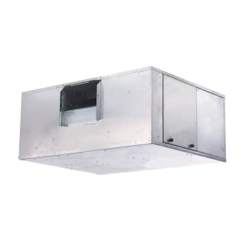
Airstream™ 42B
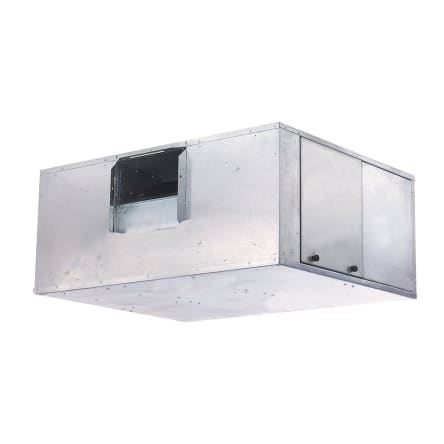

Airstream™
42B
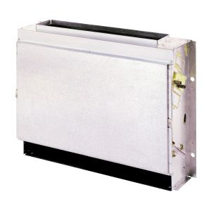
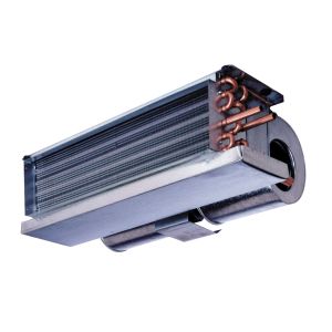
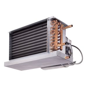
Belt Drive Fan Coils
1,019 to 6,796 m³/h
600 to 4,000 cfm
42BH - Horizontal
40BV - Vertical
The 42B belt drive fan coil units provide year-round comfort air conditioning with central station operating economy. The 42B units are designed for high-static, ducted applications, using furred-in, horizontal and vertical models
Performance Features
- Airflow capacities from 600 to 4000 cfm.
- Outside air capability with mixing box.
- Wide range of coil options for 2-pipe or 4-pipe system combinations.
- Motors available from ¼ hp to 5 hp.
- Forward-curved, centrifugal, double-inlet fans are statically and dynamically balanced at the factory.
- 2 in. pleated filter for indoor air quality.
Reliability Features
- All equipment wiring complies with NEC requirements.
- Units constructed in accordance with ETL and ETL, Canada standards.
- Optional electric heaters are fully sheathed for marine applications.
- Unit casing meets UL 181 and NFPA 90A standards.
Maintenance Features
- Stainless steel marine double drain pan ensures positive drainage during pitch and roll.
- Removable panels make access to components and connections easy.
- Label information adhered to each unit includes model, size, coil information, electrical information, and tagging data.
Installation Features
- Drives are pre-set at the factory for the specific airflow at the static pressures as ordered.
- Variable-pitch pulley adjusts at the jobsite to accommodate limited ranges of air quantities and pressures.
- Motor has an adjustable platform for easy belt adjustment.
- Knockouts are provided for hanging the horizontal units that will accept a ⅜ in. threaded rod at the top and bottom of all unit corners.
- 1-in. long supply and return duct connections.
- Single point electrical connection.
Standard Warranty
- One-year parts.
Factory-Installed Options
- Motor control only (24 v transformer, motor contactor, and terminal strip).
- Interlocking disconnect switch.
- Chilled water cooling coil.
- DX cooling coil.
- Hot water heating coil.
- Steam heating coil.
- Fully sheathed electric heating coil.
- 1 and 2-inch filter options.
- Automatic air vents and drains on water coils.
- Foil faced fiberglass insulation.
- Closed cell insulation.
- Double wall cabinet construction.
- Seismic certified construction (OSHPD & IBC).
- Motor horsepower range options.
- Condensate overflow switch.
Field-Installed Accessories
- Mixing box with base rails.
Physical Data (Sizes 06-12)
| Unit Size | 06 | 08 | 10 | 12 |
|---|---|---|---|---|
| Nominal cfm | 600 | 800 | 1000 | 1200 |
| 42BHE operating weight (lb.) | ||||
| No heat | 235 | 269 | 292 | 296 |
| With heat | 266 | 268 | 327 | 329 |
| 42BVE operating weight (lb.) | ||||
| No heat | 232 | 234 | 283 | 287 |
| With heat | 263 | 265 | 316 | 320 |
| Filters (2 in. pleated) | ||||
| Number | 1 | 1 | 1 | 1 |
| Size (in.) | 16½ x 24 | 16½ x 24 | 18¼ x 33 | 18¼ x 33 |
| Face area (sq. ft.) | 2.8 | 2.8 | 4.2 | 4.2 |
| Hydronic coils | ||||
| Size (in.) | 15 x 20 | 15 x 20 | 15 x 29 | 15 x 29 |
| Face area (sq. ft.) | 2.1 | 2.1 | 3.0 | 3.0 |
| Fins per inch | 10 | 10 | 10 | 10 |
| Coil water volume (approx. gal. per row of coil) | 0.240 | 0.240 | 0.324 | 0.324 |
| Fans | ||||
| Qty...Size (in.) | 1...9 x 4 | 1...9 x 6 | 1...10 x 4 | 1...10 x 7 |
| Hydronic coil conn. (in.) | ||||
| 8 Row (cooling) | 1 nominal
1.125 OD |
1 nominal
1.125 OD |
1 nominal
1.125 OD |
1 nominal
1.125 OD |
| 4 and 6 Row (cooling) | ¾ nominal
0.875OD |
¾ nominal
0.875OD |
¾ nominal
0.875OD |
¾ nominal
0.875OD |
| 1 Row (heating) | ½ nominal
0.625 OD |
½ nominal
0.625 OD |
½ nominal
0.625 OD |
½ nominal
0.625 OD |
| 2 Row (heating) | ½ nominal
0.625OD |
½ nominal
0.625OD |
½ nominal
0.625OD |
½ nominal
0.625OD |
| DX Coil conn. liquid line (in.) | ¼ nominal
0.375OD |
¼ nominal
0.375OD |
¼ nominal
0.375OD |
¼ nominal
0.375OD |
| DX Coil conn. suction line (in.) | ¾ nominal
0.875OD |
¾ nominal
0.875OD |
¾ nominal
0.875OD |
¾ nominal
0.875OD |
| Drain conn. sizes (in.) | ¾ MPT | ¾ MPT | ¾ MPT | ¾ MPT |
Physical Data (Sizes 16-40)
| Size | 16 | 20 | 30 | 40 |
|---|---|---|---|---|
| Nominal cfm | 1600 | 2000 | 3000 | 4000 |
| 42BHE Operating weight (lb.) | ||||
| No heat | 360 | 404 | 505 | 637 |
| With heat | 395 | 440 | 542 | 674 |
| 42BVE Operating weight (lb.) | ||||
| No heat | 337 | 412 | 504 | 606 |
| With heat | 371 | 448 | 541 | 644 |
| Filters (2 in. pleated) | ||||
| Number | 2 | 2 | 2 | 2 |
| Size (in.) | 18¼ x 21½ | 20¾ x 22 | 29 x 22 | 29 x 29 |
| Face area (sq. ft.) | 5.5 | 6.3 | 8.9 | 11.7 |
| Hydronic coils | ||||
| Size (in.) | 15 x 39 | 18 x 40 | 27 x 40 | 27 x 54 |
| Face area (sq. ft.) | 4.1 | 4.9 | 7.7 | 10.3 |
| Fins per inch | 10 | 10 | 10 | 10 |
| Coil water volume (approx. gal. per row of coil) | 0.420 | 0.492 | 0.768 | 1.020 |
| Fans | ||||
| Qty...Size (in.) | 1...11 x 10 | 1...12 x 9 | 1...12 x 12 | 1...15 x 12 |
| Hydronic coil conn. (in.) | ||||
| 8 Row (cooling) | 1 nominal
1.125 OD |
1 nominal
1.125 OD |
1½ nominal
1.625OD |
1½ nominal
1.625OD |
| 4 and 6 Row (cooling) | 1 nominal
1.125OD |
1 nominal
1.125OD |
1½ nominal
1.625OD |
1½ nominal
1.625OD |
| 1 Row (heating) | ½ nominal
0.625 OD |
½ nominal
0.625 OD |
1½ nominal
1.625OD |
1½ nominal
1.625OD |
| 2 Row (heating) | 1 nominal
1.125OD |
1 nominal
1.125OD |
1½ nominal
1.625OD |
1½ nominal
1.625OD |
| DX Coil conn. liquid line (in.) | ¼ nominal
0.375OD |
¼ nominal
0.375OD |
½ nominal
0.625 |
½ nominal
0.625 |
| DX Coil conn. suction line (in.) | 1 nominal
1.125OD |
1 nominal
1.125OD |
1½ nominal
1.625OD |
1½ nominal
1.625OD |
| Drain conn. sizes (in.) | ¾ MPT | ¾ MPT | ¾ MPT | ¾ MPT |
SEE ALSO
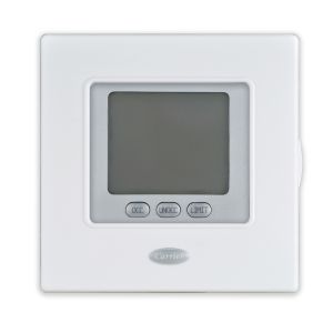
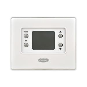
WORKS WITH
CONTROLS