Airovision™ 39HQ


Airovision™
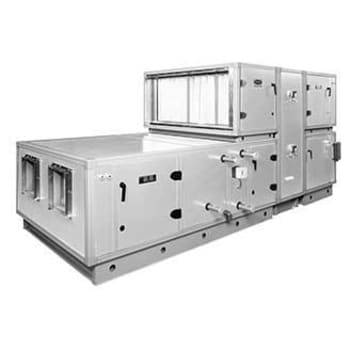
39HQ
Air Handler
Custom Double-Wall
Indoor, Outdoor & Hygienic Applications
600 to 48,500 nominal cfm
Carrier's AiroVision 39HQ Central Station Air Handler Units come with 122 different standard sizes. They combine versatility with economical, dependable performance for heating, cooling, ventilation, and VAV (variable air volume) and hygienic applications.
The construction of the Carrier air handling units consists of a frame and panels. Profiled 1-mm thick casing sides of galvanized and coated steel plates ensure a rigid and lightweight frame. The frame holds a 60-mm dual-skin casing wall with panels, doors, inspection hatches and removable center posts. The casing wall construction comes in several versions of steel plate thicknesses, material types and insulation materials used.
The characteristic of the casing wall construction must be established in accordance with EN 1886, based on measurements carried out on a model box
- Mechanical strength class D1
- Casing air leakage class L2
- Filter bypass leakage :
- F9 (front withdrawal filter)
- F9 (slide withdrawal filter)
- F7 (slide withdrawal filter -standard)
- Thermal transmittance class T2
- Thermal bridging class TB2
- Acoustics insulation
- Carrier’s AiroVision® software makes selecting and optimizing the 39HQ air handler easy.
- Country of origin: Turkey
- Air-flows ranging from 2000 m3/hr to 125,000 m3/hr
- Double skin panel construction, excellent heat preservation
- Galvanized steel construction
- The standard casing wall construction GP080 consists of 0.8 mm internal and external plating with mineral wool (glass wool) in between
- Parallel and opposed blade dampers on mixing boxes
- Horizontal and vertical draw-thru arrangements
- Multiple filtration from pleated to HEPA filters
- Chilled water, hot water, direct expansion (DX)
- Coils fabricated and tested in accordance with ASHRAE/ANSI 15 Safety Code for Mechanical Refrigeration (latest edition).
- Dual refrigerant circuits.
- Single skin drain pan insulated with 60 mm panels from all sides.
- Various coil face areas, fin densities, and circuiting arrangements
- Forward, backward, aerofoil and plug fan
- Multiple fan options
- Electric preheat available over a wide kW range
- EN 1886 “Air handling units – Mechanical performance”
- EN 13053 “Air handling units – Ratings and performance for units, components and sections Reliability Features”
- Fan performance tested and certified to DIN and AMCA Standard.
- Standard IE1 fan motor manufactured to conform IEC Standard.
- ARI 1060 and Eurovent Certified Energy Recovery Wheels
- Special stainless steel construction and other features for hygienic applications
- Units may be mounted in ceilings, closets, attics, etc.
- Casing can be broken-down to individual panels and frame members
- All service may be done through large, removable or hinged panels
- Horizontal or vertical arrangements
- Stainless steel casing
- Filter kits
- Pre filter
- HEPA filter
- Stainless steel condensate drain pan
- Coil type options:
- Chilled water coils
- Hot water coils
- DX coils
- Steam coils
- Electric heater
- Copper coils
- Coil face area, fin density, and circuiting arrangement options
- Blower motor and belt drive package
- Heat wheel
- Run around coils
- Plate Type heat exchangers
- Marine light installation kit
- Viewport installation kit
- Factory supplied VFD
- Special stainless steel construction and other features for hygienic applications
- Attenuator
- Ultraviolet band C (UV-C) germicidal lamps
- Measuring gages
| Model | Nominal Air Flow * cfm | Dimensions (mm)** | |
|---|---|---|---|
| Width | Height | ||
| 39HQ 0404 | 1,120 | 738 | 738 |
| 39HQ 0504 | 1,565 | 898 | 738 |
| 39HQ 0604 | 1,990 | 1058 | 738 |
| 39HQ 0606 | 3,195 | 1058 | 1058 |
| 39HQ 0704 | 2,415 | 1218 | 738 |
| 39HQ 0706 | 3,895 | 1218 | 1058 |
| 39HQ 0804 | 2,860 | 1378 | 738 |
| 39HQ 0806 | 4,575 | 1378 | 1058 |
| 39HQ 0808 | 6,310 | 1378 | 1378 |
| 39HQ 0906 | 5,295 | 1538 | 1058 |
| 39HQ 0908 | 7,305 | 1538 | 1378 |
| 39HQ 1006 | 5,970 | 1698 | 1058 |
| 39HQ 1008 | 8,260 | 1698 | 1378 |
| 39HQ 1010 | 10,165 | 1698 | 1698 |
| 39HQ 1106 | 6,670 | 1858 | 1058 |
| 39HQ 1108 | 9,210 | 1858 | 1378 |
| 39HQ 1110 | 11,330 | 1858 | 1698 |
| 39HQ 1206 | 7,390 | 2018 | 1058 |
| 39HQ 1208 | 10,165 | 2018 | 1378 |
| 39HQ 1210 | 12,600 | 2018 | 1698 |
| 39HQ 1212 | 15,350 | 2018 | 2018 |
| 39HQ 1308 | 11,120 | 2178 | 1378 |
| 39HQ 1310 | 13,765 | 2178 | 1698 |
| 39HQ 1312 | 16,730 | 2178 | 2018 |
| 39HQ 1408 | 12,070 | 2338 | 1378 |
| 39HQ 1410 | 15,035 | 2338 | 1698 |
| 39HQ 1412 | 18,210 | 2338 | 2018 |
| 39HQ 1414 | 21,390 | 2338 | 2338 |
| 39HQ 1608 | 13,975 | 2658 | 1378 |
| 39HQ 1610 | 17,365 | 2658 | 1698 |
| 39HQ 1612 | 21,175 | 2658 | 2018 |
| 39HQ 1614 | 24,990 | 2658 | 2338 |
| 39HQ 1616 | 28,590 | 2658 | 2658 |
| 39HQ 1810 | 19,800 | 2978 | 1698 |
| 39HQ 1812 | 24,140 | 2978 | 2018 |
| 39HQ 1814 | 28,375 | 2978 | 2338 |
| 39HQ 1816 | 32,610 | 2978 | 2658 |
| 39HQ 2010 | 22,235 | 3298 | 1698 |
| 39HQ 2012 | 27,100 | 3298 | 2018 |
| 39HQ 2014 | 31,975 | 3298 | 2338 |
| 39HQ 2016 | 36,850 | 3298 | 2658 |
| 39HQ 2212 | 30,070 | 3618 | 2018 |
| 39HQ 2214 | 35,365 | 3618 | 2338 |
| 39HQ 2216 | 40,870 | 3618 | 2658 |
| 39HQ 2412 | 33,035 | 3938 | 2018 |
| 39HQ 2414 | 38,965 | 3938 | 2338 |
| 39HQ 2416 | 44,895 | 3938 | 2658 |
| 39HQ 2418 | 49,765 | 3938 | 2978 |
*Airflow is based upon 500ft/min face velocity.
**Airway length is variable upon different component arrangements. Contact local Carrier Office for individual airway length of components.